Jafar Esmaeelian, Björn Palm, Rahmatollah Khodabandeh, Hatef Madani
KTH Royal Institute of Technology, Sweden
Hydrocarbon refrigerants such as R-290 are increasingly used in heat pumps due to their low environmental impact, but their flammability requires accurate leakage modeling. This study investigates leakage behavior under controlled liquid and vapor conditions using a simplified experimental setup. The results show that while liquid leaks initially produce much higher mass flow rates, they decrease rapidly due to pressure drop and cooling, whereas gas leaks persist longer and cause stronger internal cooling. These findings highlight the importance of transient effects and provide valuable input for improving safety models and charge-limit calculations in standards such as IEC 60335-2-89.
Introduction
The increasing adoption of low-GWP refrigerants has accelerated the use of hydrocarbons such as R-290 in heat pumps and refrigeration systems. These refrigerants offer excellent thermodynamic performance and minimal climate impact, but their flammability introduces additional safety considerations.
One of the most critical factors in assessing flammability risk is the rate at which refrigerant is released during a leak. Leakage rate determines how quickly a flammable cloud can form, how large it becomes, and how long it persists. These aspects directly influence safety standards, system design, and charge-limit calculations.
Previous studies have reported differing conclusions regarding the relative severity of liquid and vapor leaks. Some experimental programs have shown that liquid leaks can be significantly stronger due to higher fluid density, while others indicate that system behavior and phase transitions can reduce this difference. These discrepancies highlight the need for a clearer understanding of the underlying leakage mechanisms.
Test Setup and Results
A simplified approach to leakage investigation
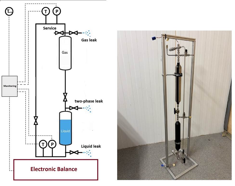
To isolate the fundamental physics of refrigerant leakage, a simplified experimental setup was developed, as shown in Figure 1. Instead of testing a complete heat pump system, a dual-cylinder configuration was used to represent the liquid and vapor regions separately. This approach eliminates the influence of system complexity, such as refrigerant migration, internal flow paths, compressor operation, and component interactions, which are known to affect leakage behavior in full-scale systems. Leakage was simulated through small holes located at different vertical positions, corresponding to gas, liquid, and intermediate (two-phase) conditions. The leakage process was monitored by measuring mass loss, pressure, temperature, and surface temperature distribution using infrared imaging. By simplifying the geometry while maintaining realistic thermodynamic conditions, the setup allows the fundamental leakage mechanisms to be studied more clearly than in full-system experiments.
Liquid leaks: high initial discharge but rapid decay
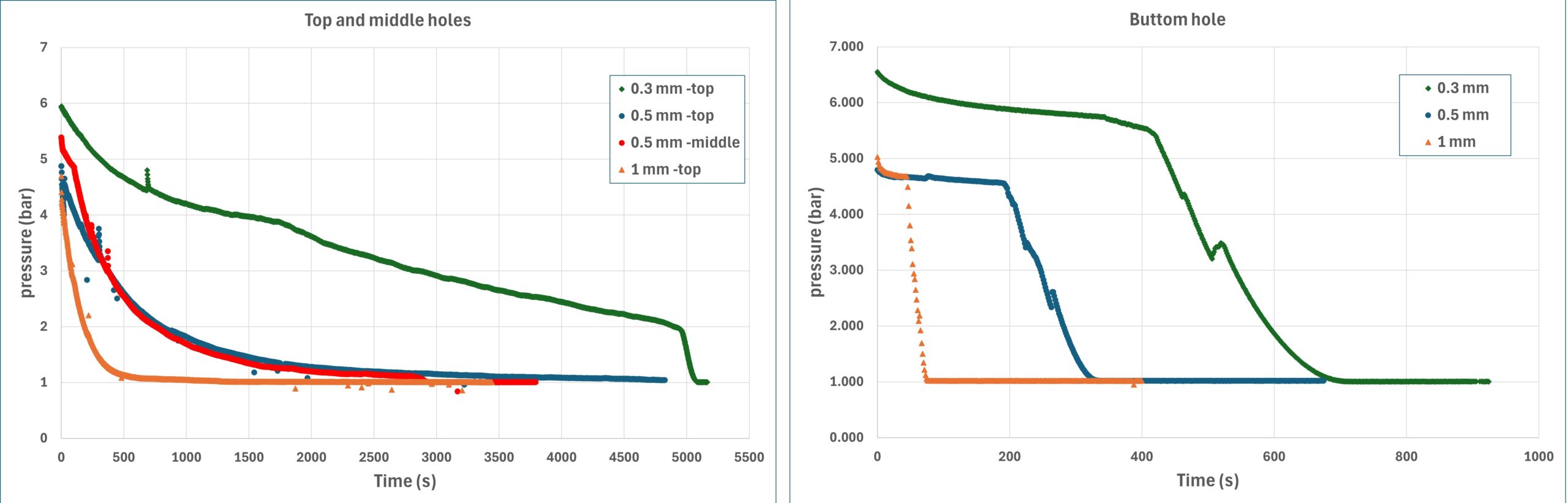
The experiments show that liquid leaks initially produce significantly higher mass flow rates than vapor leaks. This is primarily due to the higher density of liquid refrigerant at the same pressure, consistent with observations reported in large-scale ORNL and AHRTI studies [1]. Under the tested conditions, liquid leakage produced a rapid initial discharge accompanied by a steep pressure drop inside the cylinder. However, this high discharge rate does not persist. As the leakage continues, the system cools rapidly due to evaporation, leading to a decrease in pressure and a corresponding reduction in leakage rate. In addition, a substantial portion of the liquid undergoes flashing at the leak opening, forming a two-phase mixture that reduces the effective discharge density. Similar transient effects have been discussed in previous leakage investigations of hydrocarbon refrigerants [2]. The resulting pressure evolution for liquid and gas leakage conditions is shown in Figure 2. Liquid leakage produces a rapid initial depressurization, while gas leakage results in a slower and more gradual pressure decay.
Gas leaks: lower intensity but longer duration
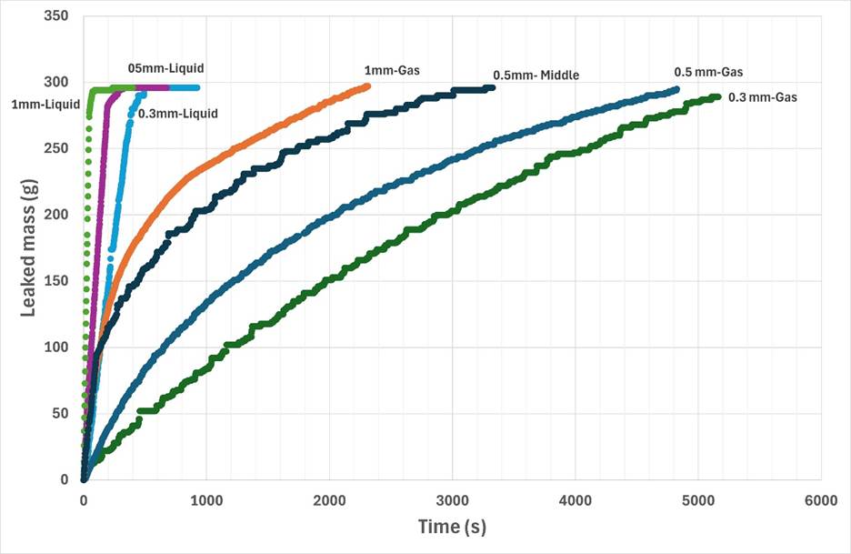
Gas-phase leakage behaves differently. Although the initial leakage rate is much lower, the discharge continues over a significantly longer period. This is because the pressure decreases more gradually and the mass flow is limited by compressible-flow effects. An important observation is that gas leaks lead to stronger internal cooling than liquid leaks. This occurs because evaporation predominantly takes place inside the system, continuously absorbing heat from the surroundings. This internal cooling further reduces pressure and progressively slows the leakage process. The cumulative released mass for different leakage conditions is presented in Figure 3. While liquid leaks release refrigerant rapidly during the initial stage, gas leaks continue discharging refrigerant over a much longer period.
Where evaporation occurs matters
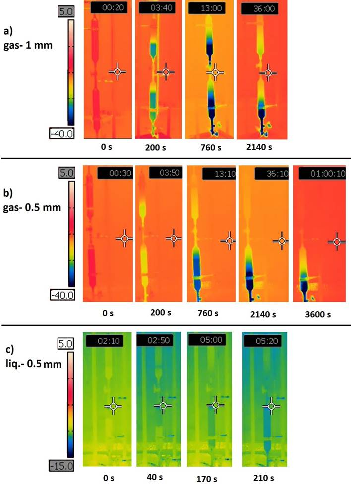
Infrared imaging revealed that the location of evaporation plays a crucial role in determining system behavior, as illustrated in Figure 4. Interestingly, the strongest cooling was not observed directly at the leak hole, but rather near the liquid surface inside the cylinder, where evaporation occurred. For gas leaks, evaporation mainly takes place inside the system, resulting in substantial internal cooling and a strong reduction in wall temperature. In contrast, during liquid leakage, a large portion of evaporation occurs outside the system after the refrigerant exits the orifice. As a result, internal cooling is less pronounced despite the significantly higher initial mass flow rate. These observations demonstrate that leakage behavior is governed not only by pressure and orifice size, but also by the interaction between phase change, evaporation location, and heat transfer.
Limitations of simplified leakage models
Leakage is often modeled using simplified equations assuming constant pressure and steady flow. However, the experiments clearly demonstrate that refrigerant leakage is a transient process influenced by pressure decay, temperature changes, and phase transitions. In particular, the commonly used incompressible liquid-flow model tends to overestimate leakage rates once flashing occurs and the discharge becomes two-phase. Conversely, compressible choked-flow models provide better agreement for vapor-phase leakage but do not fully capture the early behavior of liquid leaks. These findings suggest that leakage source models used in safety analysis should account for transient thermodynamic effects and phase transitions rather than relying solely on steady-state assumptions.
Implications for safety standards
The present findings have direct implications for safety standards such as IEC 60335-2-89 [3] and for ongoing work within IEA Heat Pumping Technologies Project 64. Current safety calculations often assume constant upstream pressure and simplified leakage behavior. However, the experiments show that pressure decay and internal cooling reduce leakage rates over time compared with constant-pressure assumptions. This means that the duration and magnitude of refrigerant release may be overestimated if transient effects are neglected. A better understanding of leakage dynamics can improve refrigerant leak modeling, leading to more accurate predictions of refrigerant concentration and potentially reducing unnecessary conservatism while maintaining adequate safety margins.
Conclusions
This study demonstrates that leakage behavior of R-290 is strongly dependent on phase conditions, heat transfer, and transient thermodynamic effects. While liquid leaks initially produce higher discharge rates, they decrease rapidly due to pressure reduction. Gas leaks, on the other hand, are less intense but persist longer and result in stronger internal cooling. These findings show that leakage cannot be accurately described using constant-pressure or steady-flow assumptions. Instead, it should be treated as a dynamic process influenced by phase change and energy transfer. The results provide valuable insight for improving leakage models used in safety standards and support ongoing efforts to refine risk assessment methods for flammable refrigerants.
Author contact information
| Name | Jafar Esmaeelian |
| Title | PhD Student |
| Affiliation | KTH Royal Institute of Technology |
| Postal address | Stockholm, Sweden |
| E-mail address | jafare@kth.se |
References
[1] V. R. Baxter et al., Refrigerant Leak and Ignition Testing for Flammable Refrigerants, ORNL/TM-2018/1058, Oak Ridge National Laboratory, 2019.
[2] D. Colbourne and K. W. Suen, “Refrigerant leak characteristics of commercial refrigeration systems,” International Journal of Refrigeration, vol. 27, no. 4, pp. 864–873, 2004.
[3] International Electrotechnical Commission, IEC 60335-2-89: Household and Similar Electrical Appliances – Safety – Part 2-89: Particular Requirements for Commercial Refrigerating Appliances and Ice-Makers with an Incorporated or Remote Refrigerant Unit, 3rd ed., Geneva, Switzerland, 2022.