Riley B. Barta & Davide Ziviani, Ray W. Herrick Laboratories, Purdue University, Mechanical Engineering, USA
As hydrocarbon refrigerants continue to gain popularity for vapor-compression cycle applications, a safe and reliable research and development infrastructure for testing A3 refrigerants and their systems becomes critical. This article will provide background and examples for experimental infrastructure designed to characterize systems and components using A3 working fluids, as well as the fluids themselves. Applications range from ultra-low-temperature refrigeration to high-temperature heat pumps, and perspectives from North America, Asia, and Europe are offered.
Introduction
Motivation for the Use of Flammable Refrigerants
As refrigerant phase-outs and increasingly scrutinizing environmental legislation continue to gain momentum around the world, vapor compression cycle developers find themselves with two primary paths to regulatory compliance: low-Global Warming Potential (GWP) synthetic refrigerants, such as Hydrofluoroolefins (HFOs) and mixtures of HFOs and Hydrofluorocarbons (HFCs), or the so-called natural refrigerants, such as hydrocarbons, carbon dioxide, water, and air. In addition to GWP, another key characteristic of these refrigerants is their flammability, which is generally classified according to ISO 817 [1] or ASHRAE 34 [2]. A is less toxic, and B is more toxic; 1 has no flame propagation, 3 is extremely flammable, 2 is generally flammable, and 2L is mildly flammable, with a burning velocity under 10 cm/s. The reasons for selecting flammable or non-flammable, synthetic or natural materials are debated and largely depend on the application and the trade-offs between volumetric capacity (i.e., heat exchanger and compressor sizing requirements) and GWP [3].
With respect to methods of characterizing thermal systems, the scope of this article will focus on vapor compression cycles, including ultra-low temperature (ULT) applications (e.g., vaccine cooling), domestic and industrial refrigeration, and heat pumps ranging from cold climate (e.g., ambient temperatures below –20 C) all the way to high-temperature heat pumps (e.g., providing heat at 200
C). Full system characterization is often carried out via psychrometric chambers to simulate the targeted airside. Compressor characterization is often conducted using a calorimeter or a hot-gas bypass test stand, while heat exchanger characterization can be performed in smaller test loops, depending on the secondary fluid type. At the fluid level, thermo-physical property measurements, development of the so-called Daniel Plots relating density, viscosity, and vapor pressure, and flammability tests are of primary interest. While this list isn’t exhaustive, it captures the majority of standard test stand types for vapor compression cycle applications.
Given the legislative and market developments driving the development of vapor compression cycles with low-GWP refrigerants, there is a need to openly share infrastructure development techniques for the characterization of hydrocarbon and A3 refrigerants to safely and sustainably drive research and development in this field forward. In this context, this article will focus on the development of experimental infrastructure specifically designed for carrying out system, component, and fluid characterization of A3 refrigerants. The theory behind safety standards will be summarized, with concrete examples provided.
Development Experimental Test Infrastructure
Charge Calculations
The first step in developing any experimental infrastructure to characterize flammable or toxic refrigerants is to understand (a) the safety classification of the working fluid via ISO standard 817 or ASHRAE standard 34 and (b) to determine the amount of charge (mass or refrigerant) the space where the investigation is to take place can safely accommodate via ISO standard 5149 [4] or ASHRAE standard 15 [5]. The nuances of the charge determination are numerous and depend on factors such as the space designation (e.g., is it publicly accessible or accessible only to trained personnel?) and the so-called Refrigerant Concentration Limit (RCL). The RCL represents the maximum refrigerant concentration necessary to create a dangerous atmosphere, whether via flammability (where the Lower Flammability Limit (LFL) is the determining factor) or toxicity (where the Acute Toxicity Exposure Limit (ATEL) is the determining factor). It should be noted that, depending on space classification, various fractions of the LFL can be considered limiting. For example, in the open laboratory settings reviewed here, the authors set the RCL to the conservative limit of 25% LFL or the ATEL, whichever was lower. Once the RCL has been determined, the volume of the space is used to determine the allowable charge. It cannot be emphasized enough that this description is meant to be a general overview of the process, not a fixed rule and calculation, and that each and every experimental setup and design should be designed per the applicable safety standards.
System Characterization
For vapor compression cycles that utilize air as the heat sink, heat source, or both, testing infrastructure is required to vary air temperature and humidity and characterize system performance across a range of controlled operating conditions. This infrastructure is generally referred to as a psychrometric chamber. In regions of the world where air is used as both the source and sink, such as North America, split systems and mini-split systems used in southern Europe and Asia, a pair of psychrometric chambers is often desired to simultaneously control indoor and outdoor conditions seen by the vapor compression cycle. In parts of the world that use air as the heat source and to heat a water circuit, such as central and northern Europe, only one chamber is needed.
To test A3 refrigerants in psychrometric chambers, further considerations are needed in addition to concentration calculations, as the internal volume of the chambers is generally quite small, such that a potentially dangerous concentration of A3 refrigerant could accumulate with a charge lower than necessary for larger vapor compression systems (e.g., residential heat pumps). Therefore, additional calculations based on the required airflow rate to reduce the charge concentration within a given time are necessary. Furthermore, surface temperatures of heating elements need to be checked and often reduced via sheaths to ensure the surface temperatures remain below the lowest auto-ignition temperature of the proposed A3 fluids to be tested. While Propane’s auto-ignition temperature is approximately 470 C, n-Pentane’s auto-ignition temperature of 260
C can present notable challenges in this respect. Finally, refrigerant leak sensing to sound an alarm and automatically engage emergency ventilation, static-electricity-reducing bracelets, and documentation of refrigerant charges in systems are among the necessary additional measures.
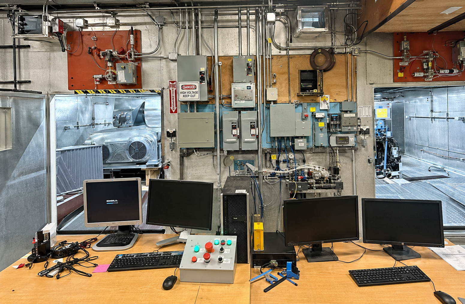
To provide a concrete example, Figure 1 shows a photo of the pair of A3 psychrometric chambers located at the Ray W. Herrick Laboratories. These chambers have been modified with all of the measures described in the previous paragraph and can safely test systems with approximately 3.2 kg of Propane and nominal capacities 15 kW, with temperatures and humidities ranging from -20 C to 52
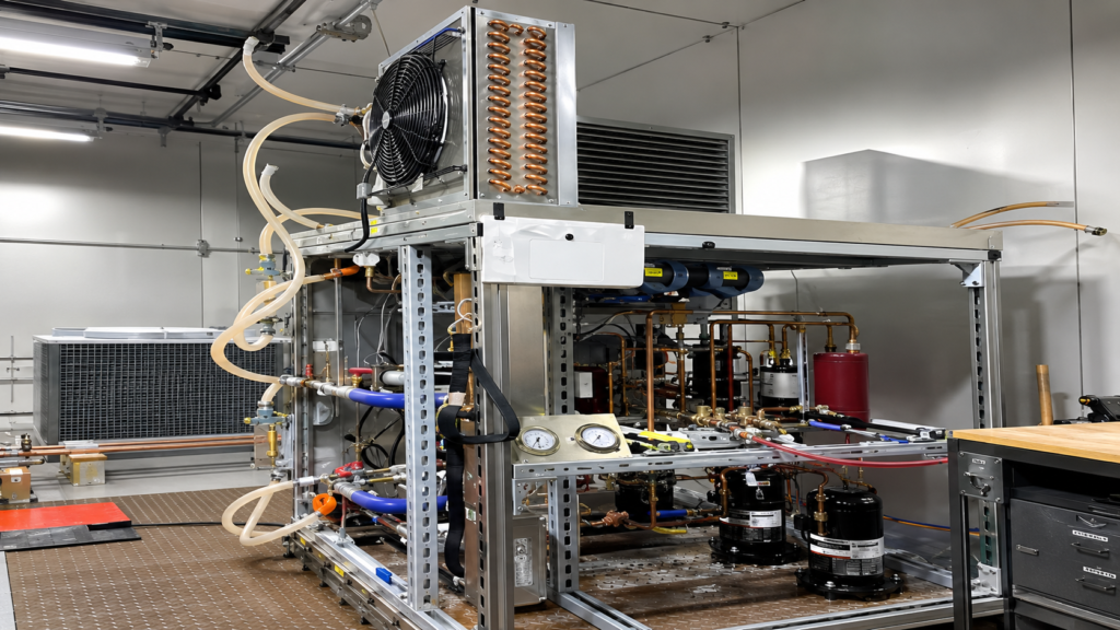
C and 25% – 95%, respectively [6]. The lessons learned and best practices from this modification process are summarized in Dhillon et al. [7]. Furthermore, an example of a cold-climate heat pump connected to glycol-based secondary loops for testing below -25 °C start-up conditions using a multi-stage propane vapor-compression cycle is provided in Figure 2 to illustrate the diverse testing capabilities [6,7].
Compressor and Heat Exchanger Characterization
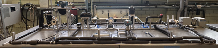
For compressor and heat exchanger testing using A3 refrigerants at the Ray W. Herrick Laboratories, the RCL method determined the allowable test stand charge. Two examples are hot-gas bypass test stands and two-phase pumped loops for compressors and heat exchangers, respectively. These test stands enable efficient, fast characterization of component performance. Key points here were to ensure that any sources of sparks were eliminated from the test stand and that the room volume where the test stands are situated allows for a meaningful A3 refrigerant charge, assuming a 25% LFL limit. An example of a pumped two-phase loop designed to measure composition shifts in working-fluid mixtures, with removable test sections for gas chromatography, is shown in Figure 3 [8].
Fluid Characterization
At the fluid level, two primary experimental setups have been developed at the Ray W. Herrick Laboratories. The first focuses on thermophysical property characterization of refrigerant mixtures with and without compressor lubricants, and the second on the experimental characterization of refrigerant flammability.
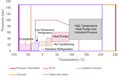
The thermophysical properties that can be measured are vapor pressure, density, viscosity, and speed of sound. Measurements can be taken from -80 C to 190
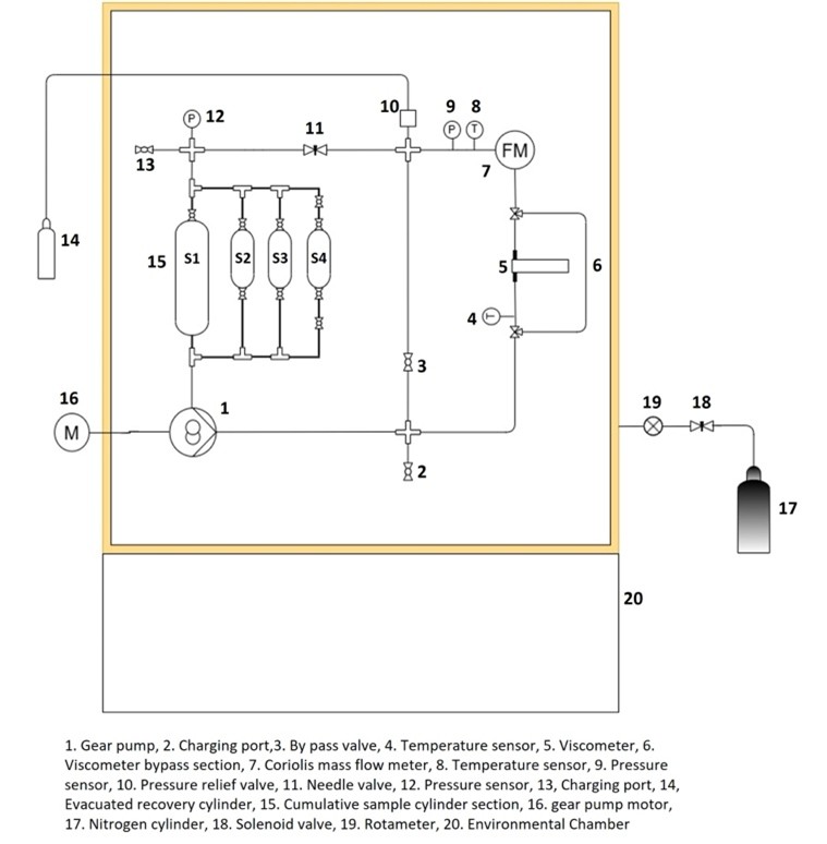
C, and the pump motor and other electronics are therefore located outside of the chamber to ensure that the refrigerant circuit remains inside the chamber [9]. High-temperature, non-sparking cables and connectors were selected, and stainless-steel sheaths were used to cover wires to sensors that didn’t offer non-sparking models. As with the psychrometric chambers, the chamber in which the thermophysical property measurement circuit is placed has sheaths on the heating elements to make sure that the surface temperature remains below the auto-ignition temperature of the A3 refrigerants to be tested. The temperatures and pressures over which select thermophysical properties can be reliably measured is provided in Figure 4.
Due to the relatively small volume of the chamber, it was decided that excess nitrogen should be pumped into the chamber to prevent the atmosphere from combusting upon a sudden release of charge. To mitigate combustion risks associated with flammable refrigerant leaks, the experimental chamber was maintained as an inert environment throughout the duration of testing. According to safety standards established by the National Fire Protection Association (NFPA 69, Annex C) [10], each flammable refrigerant is characterized by a Limiting Oxygen Concentration (LOC), below which combustion cannot be sustained when an inert diluent such as nitrogen (N₂) is used.
The chamber is equipped with a dedicated nitrogen inlet port connected to a nitrogen cylinder; the nitrogen purge flow is regulated using an inline rotameter, while an electronically actuated solenoid valve provides on/off isolation of the nitrogen supply. Because the chamber is not perfectly leak-tight, oxygen ingress occurs gradually over time. The rate of oxygen concentration increase was experimentally characterized over defined intervals using the oxygen sensor. In parallel, the nitrogen flow rate required to restore the oxygen concentration to the desired level was quantified. This information was then used to establish a controlled purging schedule, allowing estimation of both the frequency and duration of nitrogen charging required to maintain safe operating conditions. If required, this process can be automated through a LabVIEW-based control scheme to maintain a consistently inert atmosphere. Based on this approach, periodic nitrogen purging was implemented to maintain the oxygen concentration within a conservative range below the LOC. This inerting protocol is particularly critical during low-temperature operation (e.g., below −40 °C), where thermal contraction of sealing materials and metallic components increases the likelihood of refrigerant leakage. Furthermore, system overpressurization was addressed by a high-pressure relief valve (PRV) that discharged directly into an evacuated recovery cylinder rather than into the lab space.
A schematic of the property measurement setup is provided in Figure 5.
Flammability Characterization
Along with property evaluations and both component- and system-level investigations, it is important to understand the flammability behavior of both pure refrigerants and their mixtures. To this end, two sets of experimental facilities have been developed to support the research surrounding ignition sources, flame propagation, sensing and safety, the effect of lubricants, additives, and secondary fluids, among others. The ASHRAE Standard 34 classifies a refrigerant’s flammability by using the ASTM E681-09 (Standard Test Method for Concentration Limits of Flammability of Chemicals) test setup [11]. As illustrated in Figure 6(left), the flammability test takes place in a 12-liter glass flask in which a mixture of refrigerant and air is introduced, and a small spark between electrodes causes the mixture to ignite. The flammability is determined with respect to a cone angle of 90°. While this is a standardized test method, it often does not reflect real-life conditions. To this end, 250-liter blast chambers is also utilized to conduct larger-scale flammability tests [12]. As shown in Figure 6(right), the spherical chamber located at the Zucrow Laboratories is air-tight with various optical access ports to visualize the flame front from different angles and enable laser spectroscopy techniques to be applied to measure byproducts.
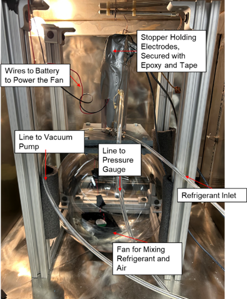
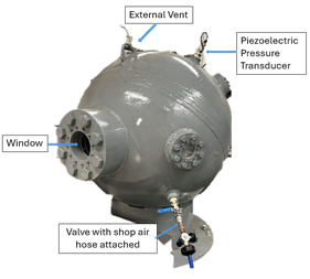
Figure 6: (6a) View of the 12-liter flask for the ASTM E681-09 method of test inside a controlled chamber. (6b) Blast chamber modified for use in testing refrigerant flammability limits.
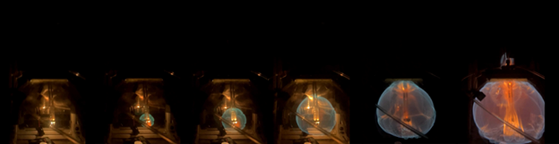
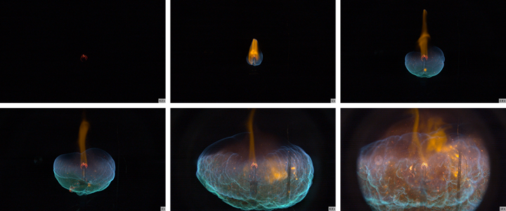
These facilities enable quantitative assessments of the flammability characteristics of the refrigerant blends that will inform future standards, building codes, and OEMs. Figure 7 illustrates an ignition sequence of 1 gram of Propane after ensuring well mixing with the internal fan. Whereas Figure 8 shows a similar ignition pattern for Propane, within the larger blast chamber.
Conclusions
This article provided background and a detailed overview of experimental methods for safely and accurately characterizing A3 refrigerants, their mixtures with lubricants, and the components and systems in which they are used. When the appropriate safety standards are considered, accurate characterization of A3 fluids, components, and systems can be achieved. While research in this space continues to gain momentum, further efforts are needed to develop safety standards for end applications and building codes to broaden acceptance of thermal systems using A3 refrigerants.
Author contact information
| Name | Riley B. Barta; Davide Ziviani |
| Title | Assistant Professor of Mechanical Engineering; Associate Professor of Mechanical Engineering |
| Affiliation | Ray W. Herrick Laboratories, Purdue University |
| Postal address | 177 S. Russell St., West Lafayette, IN 47907 |
| E-mail address | bartar@purdue.edu; dziviani@purdue.edu |
References
[1] International Organization for Standardization. (2024). ISO 817:2024: Refrigerants—Designation and safety classification (4th ed.). ISO.
[2] American Society of Heating, Refrigerating and Air-Conditioning Engineers. (2024). ANSI/ASHRAE Standard 34: Designation and safety classification of refrigerants. ASHRAE.
[3] Issa, A. A., Spale, J., Groll, E. A., & Ziviani, D. (2025). Navigating long-term use of refrigerant blends in unitary air-source heat pumps for colder climates. ASHRAE Transactions, 131, 333–341. https://doi.org/10.63044/s25nav37
[4] International Organization for Standardization. (2014–2022). Refrigerating systems and heat pumps—Safety and environmental requirements (ISO 5149, Parts 1–4). ISO.
[5] American Society of Heating, Refrigerating and Air-Conditioning Engineers. (2024). ANSI/ASHRAE Standard 15: Safety standard for refrigeration systems. ASHRAE.
[6] Issa, A. A., Liang, C., Liu, H., Groll, E. A., & Ziviani, D. (2025). Experimental analysis of a liquid-to-liquid two-stage R290 heat pump system for residential cold-climate applications. Applied Thermal Engineering, 278, 127223. https://doi.org/10.1016/j.applthermaleng.2025.127223
[7] Dhillon, P., Kurtulus, O., Liang, C., Shah, V., Horton, W. T., & Braun, J. E. (2022). Lessons learned from retrofitting a psychrometric facility for testing of HVAC&R equipment with flammable refrigerants. Proc. of the International Refrigeration and Air Conditioning Conference at Purdue, (Paper 2478). https://docs.lib.purdue.edu/iracc/2478
[8] Shepard, K.A., Cox, J.M., and Barta, R.B. (2025). Test stand and model developing for assessing two-phase flow of low-GWP zeotropic refrigerant mixtures with lubricants. Proc. of the 7th IIR Conference on Thermophysical Properties, College Park, Maryland, June 15 – 18, 2025. DOI: 10.18462/iir.tptpr2025.1106
[9] Venkatesan, G.B. and Barta, R.B. (2025). Experimental investigation of thermophysical properties of low-global warming potential refrigerant lubricant mixtures across extreme temperature ranges. Proc. of the 7th IIR Conference on Thermophysical Properties, College Park, Maryland, June 15 – 18, 2025. DOI: 10.18462/iir.tptpr2025.1107
[10] National Fire Protection Association. (2019). NFPA 69: Standard on explosion prevention systems (Annex C). https://www.nfpa.org
[11] ASTM International. (2023). Standard test method for concentration limits of flammability of chemicals (vapors and gases) (ASTM E681-09(2015)). ASTM International.
[12] O’Malley, C.E., Ferguson, R.E., Velazquez, E., Tanguay, S.H., Son. S.F., Ziviani, D. (2026). An Investigation of Flammability in Low-GWP refrigerant Blends for Military transport Applications. ASHRAE Journal.